This is the second part of a series investigating the use of optical sensors for robot odometry.
In part one of this project I pulled apart an old Microsoft Intellimouse for the optical chip and managed to extract some readings using an Arduino Uno. The aim now is to repackage those components in a way that they could be mounted underneath a small wheeled robot.
Mentioned in the previous article, I would have like to have simply mounted the components to some veroboard, but since the optical sensor chip has an awkward layout and there are no off-the-shelf breakouts, it meant I’d have to design my own PCB.
My only experience of PCB design/manufacture comes from taking a ‘Systems & Control’ GCSE almost 15 years ago. Our classroom had a crusty looking etching tank sitting in the corner, but suffice to say we weren’t let anywhere near it. Fast-forward to the present and I now work for an electronics company with people who do this sort of thing on a daily basis.
I reached out for recommendations and EAGLE was suggested by a number of people, so armed with a tutorial from Sparkfun I set about my PCB design. A lot of thanks also has to go to the London Hackspace and their wiki for some great information about PCB design and fabrication.
Remember when I said that the optical sensor has an awkward layout? Well that meant there were no similar chips in the built-in libraries – so I had to design this component from scratch, making sure all the holes for the legs were in exactly the right places along with the big hole for the sensor to actually see through. The trusty calipers got a lot of use here!
On the whole though, using EAGLE was relatively painless and I went through a few iterations of the design before I settled on something I was happy with. Below is a comparison of my first attempt vs. my final design.
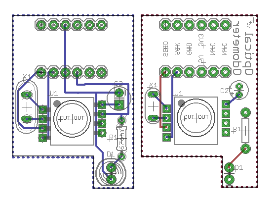
You’ll notice how much less wiring there is on the right-most, learning how to use ground-planes really simplified things! The oscillator (X1) sits on the left of the main chip (U1), along with the capacitor (C2), resistor (R1) and LED (D1) on the right of the chip. At the top, I decided to add space for a logic-level converter, which will mean I can use this board at the designed 5V with an Arduino, or step the voltage down to 3V3 for use with a Raspberry Pi.
After a lot of back and forth I was ready to send the PCB for fabrication. I decided to go with Ragworm since they’re based in the UK, pretty cheap and offered a relatively quick turnaround. Only seven days after submitting my order they shipped my PCB.
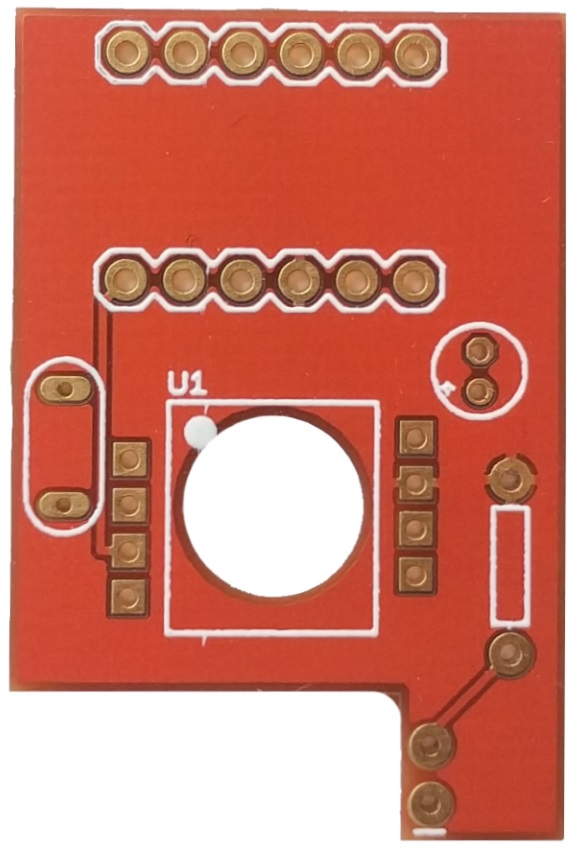
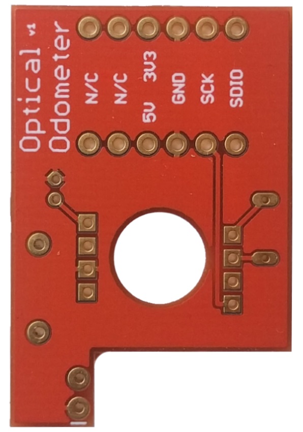
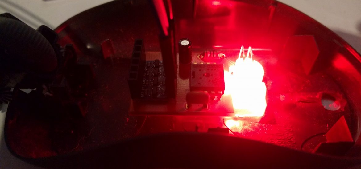
You might notice that some of the component labels are missing from the top of the board. Apparently despite all my checking, I’d added these to the wrong layer in EAGLE. All in all I’m very pleased with the result and it only cost me a little over £5. Here it is populated with the components that were extracted from the mouse:
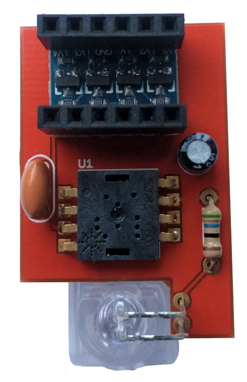
Fortunately the optical sensor fit perfectly – this was something I worried about right until I slotted the chip in!
The logic-level converter at the top is something I picked up from Ebay fairly cheaply. I replaced the male header it came with in favour of a female header that would make testing a little easier. Finally I hooked it up to my Arduino and gave it a test drive. Wrong register values in the software caused me a mild panic, but once they were corrected it seemed to work pretty well.
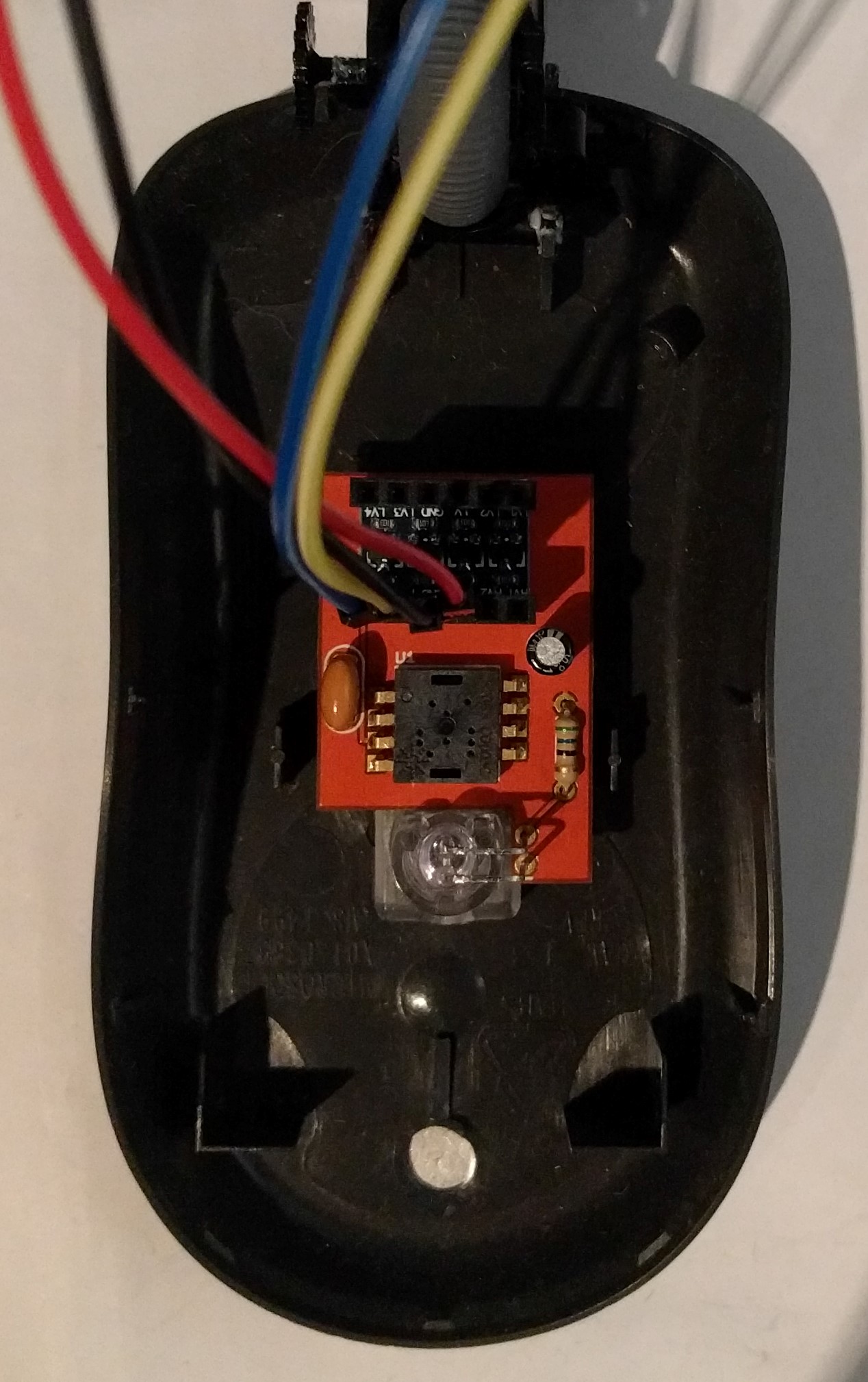
The next step will definitely involve some 3D printing as I figure out how to mount this on my rover. Stay tuned!