Having the Perturbator and Meeple pin badges under my belt, it was finally time to try something a little bit more complicated.
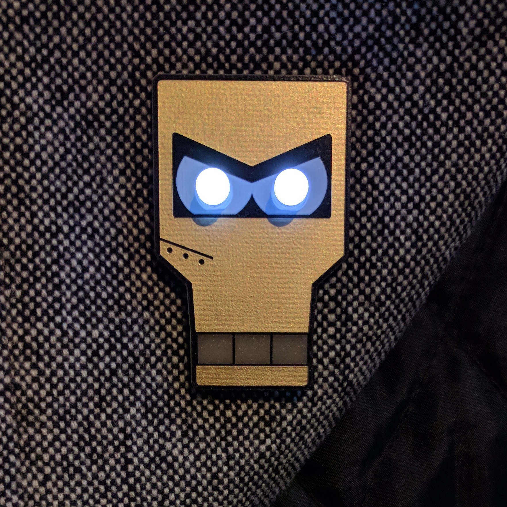
Inspired by Day of the Geek badge that I own, I thought I’d try a memorable robot from Futurama: Francis X. Clampazzo.

There were a lot of robots from Futurama that I could have chosen but I figured that the ENIG finish of a PCB would lend itself really well to the bronze colour of Clamps.
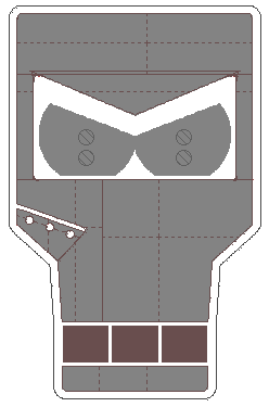
Armed with some reference photos I first laid the whole design out in Inkscape, using the layers to differentiate between copper, FR4, silkscreen and soldermask.

The appearance of Clamps seems to vary episode-to-episode, but after a few iterations I ended up with an amalgam that I was happy with. As ever the process of importing these polygons into EAGLE is a bit tricky but I persevered. I ultimately decided that I’d use the ENIG finish for Clamps’ metal surface and exposed FR4 for his mouth, though for a while I did consider the reverse. Black soldermask provides an outline and white silkscreen would be used for the eyes.
With my previous badges, this would be where I’d send it off for fabrication, but before I could send this board off I needed to add the components.
The trickiest part of this process turned out to be the battery holder, finding a surface mount component that was the right size took some time but I finally found one that I liked over at Proto-PIC. They also happened to have some tiny surface mount slide switches. Not strictly necessary, but it would give me an easy way to turn the LEDs off without having to remove the battery. Handily these were both Sparkfun parts and so they were included in their EAGLE libraries. I did have to tweak the footprint for the switch slightly to remove the two small drills holes that were meant to accommodate posts on the switch.
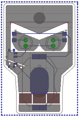
After two 5mm LEDs, the last things to add were the resistors. A lot of LED badges do without these, but I was keen to draw out the life of my old 2032 batteries as long as I could. I was initially unsure about what size I’d be able to solder by hand but eventually went with a couple of 1206 surface mount resistors. Here’s how the board looked in EAGLE:
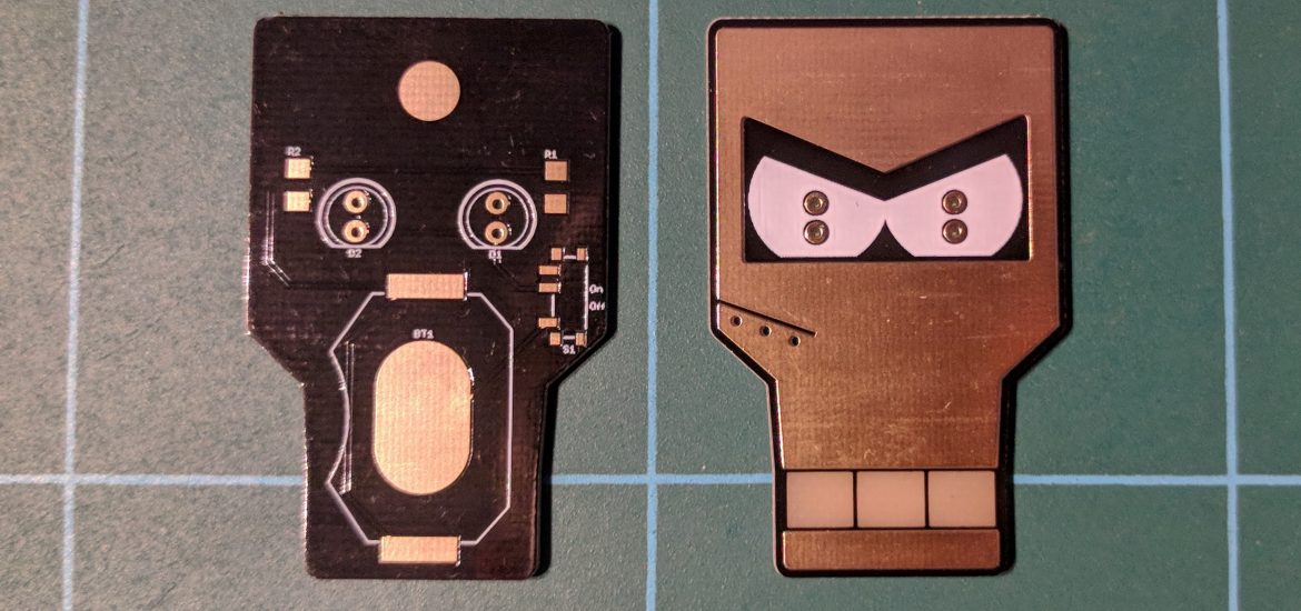
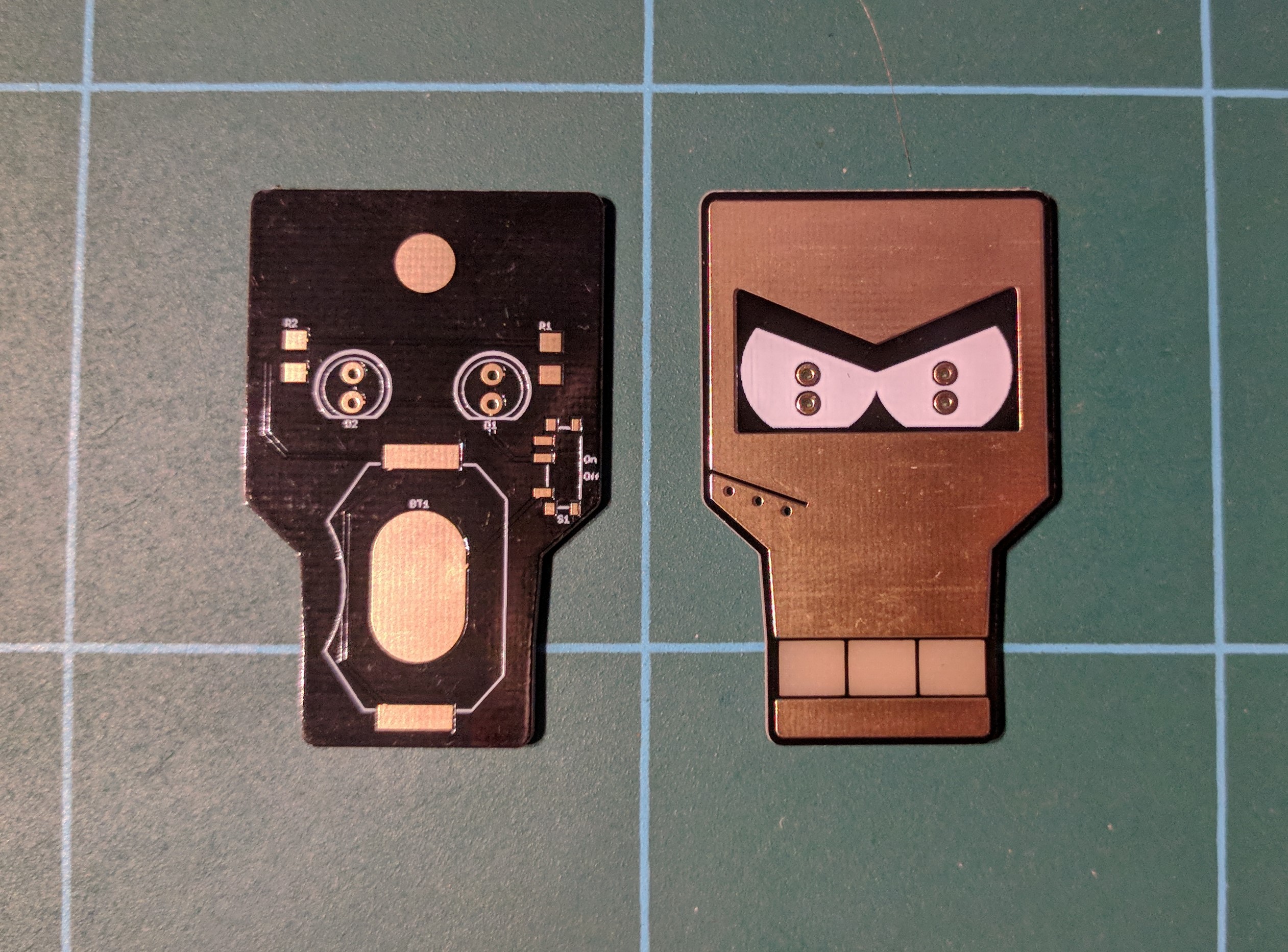
Unfortunately at this point I realised were were in the middle of Chinese New Year celebrations which would affect the turnaround of the PCB. Nevertheless I sent it off to Elecrow for fabrication and started ordering the remaining components. After a few weeks of waiting, the boards turned up:
| Order submitted | February 12th |
| Dispatched | March 2nd |
| Received | March 7th |
I’m really happy with them, especially the colour of the FR4 and they worked out at just over £2 per board.
Next was the bit I was dreading. This would be my first attempt at soldering surface mount components by hand. I started off with the coin cell holder and moved onto the resistors. These were pretty straight-forward, I’d load some solder onto one pad, and tack down one side of the component, then I’d feed some solder on to the remaining pad. Before soldering the switch I had to sand off the little posts on the underside. The tiny legs proved quite difficult to solder and I ended up having to probe the board with a multimeter to figure out which of the legs wasn’t soldered properly. I neglected to solder all the extra feet on the switch as it felt pretty sturdy. Finally I attached the pin with superglue and gave the front of the badge the usual clearcoat to protect it.
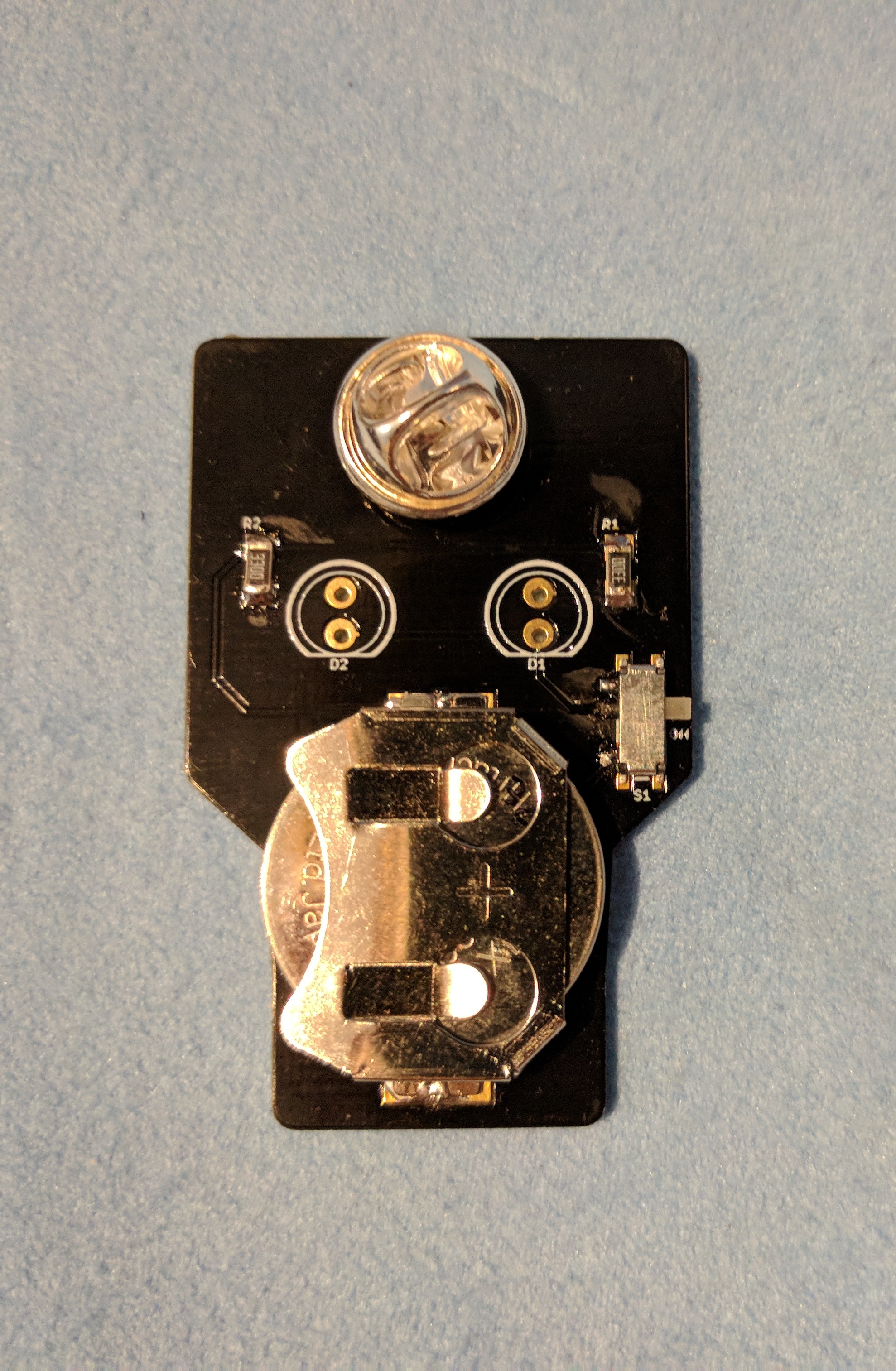
The board could do with a bit of a clean up to remove flux, but it works!
For now the LEDs remain unsoldered as I can’t decide between these flat topped LEDs and some white diffused LEDs that I ordered. I also want to try and draw a square pupil on the top of each LED as a finishing touch.
These are now for sale on Tindie in limited quantities. I’m forever coming up with new badge ideas and I’m really tempted to do the rest of the Robot Mafia to complement this badge!