The last time I worked on this project was two years ago and it ended up in a box after I tore one of the pads off. I’ve had some spare time recently so I decided it would be fun to solder 120 LEDs on a fresh PCB.
Before I could get started I needed to recycle the LEDs from the damaged PCB. After destroying the first few I remembered I owned two soldering irons. Dual-wielding soldering irons got the rest of them off without issue.
Over the course of a couple of Twitch streams, I soldered 120 LEDs (60 yellow and 60 red LEDs) and then wired the HT16K33 LED driver board to the PCB. This time around I decided to try some fine enamelled wire, which apart from being a little tedious to strip the enamel from, turned out to work really well. It hopefully avoids the problem I had last time where I over-torqued a wire and ripped a pad off.
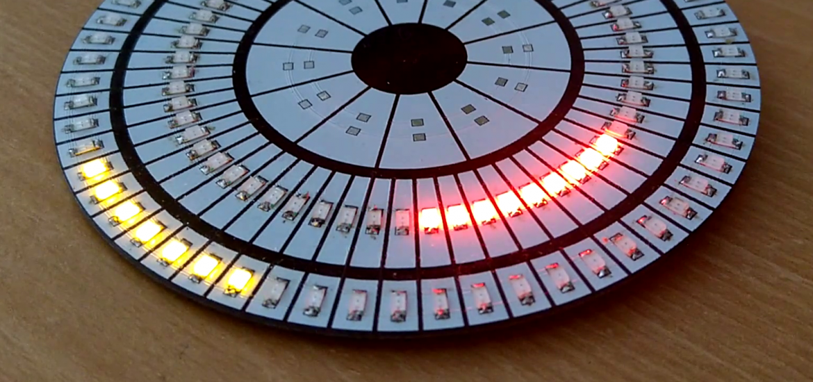
This PCB is separated into two 8×8 LED arrays and a single row of 12 LEDs arranged in circles. I soldered some spare header pins between the cathodes of the two arrays, to make a single large 16×8 array. This meant not having to solder up a second driver board.
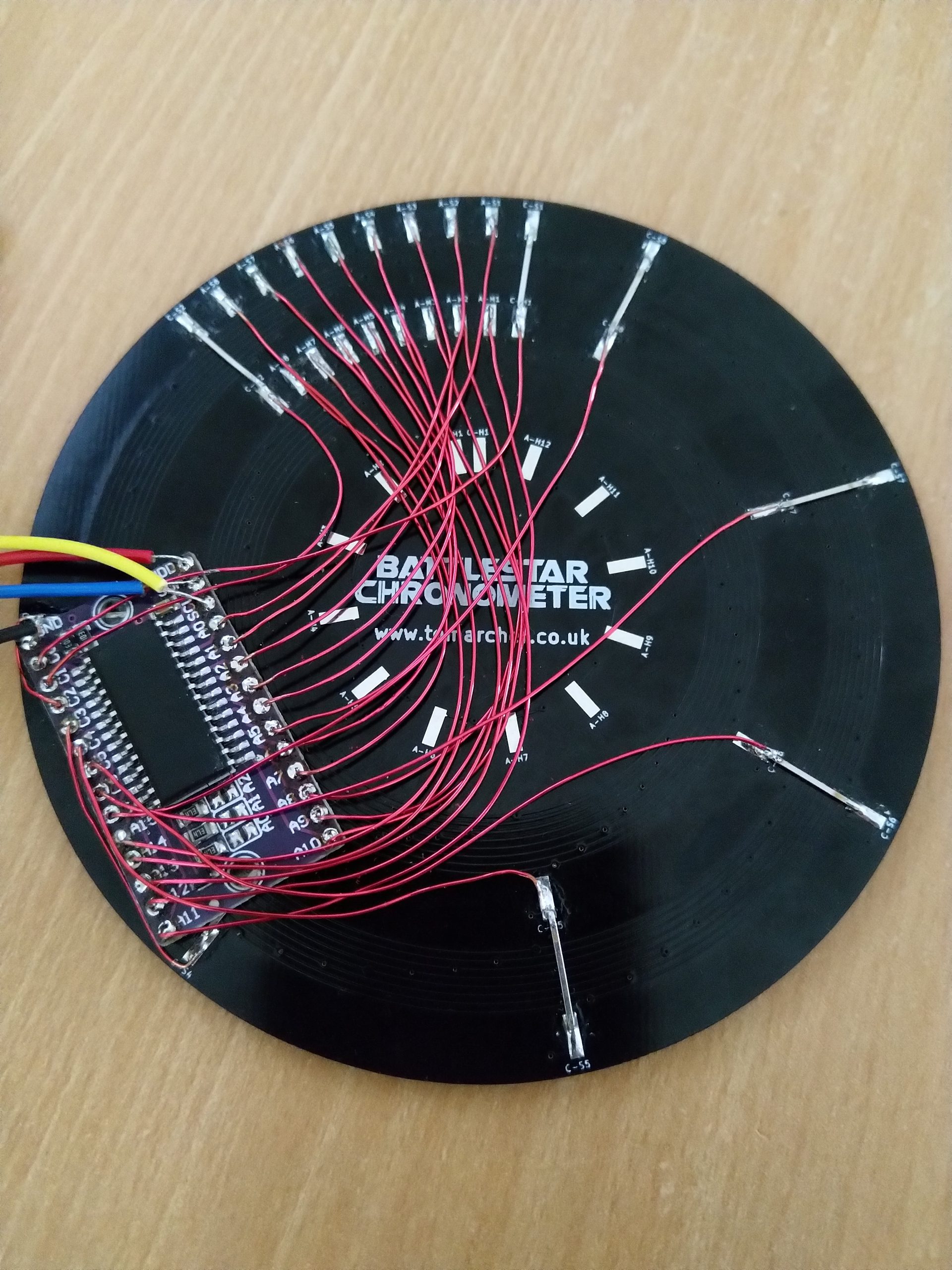
I again wired the driver board up to a logic level shifter to drop the I2C voltage from 5V to 3V3 so I could drive everything from a Raspberry Pi and then grabbed the Python library from Adafruit.
The first test showed a handful of red LEDs that didn’t light up, a couple of these were just bad solder joints, but the others were terminal so they had to be swapped.
After an afternoon of coding I came up with a few different modes:
The dual Larson scanner was a real brain-bender but I eventually figured it out. Now that I’ve got some good example code I think I’m ready to get my remaining boards listed on Tindie. Be warned though, this project is not for the faint-hearted!